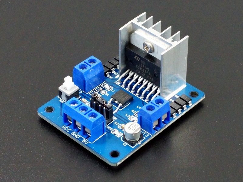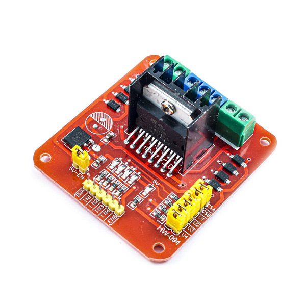

Other Extensions: control of direction indicators, the logic part of the plate to take power interfaceġ x L298N Stepper Motor Driver Controller Board Module.Driver Board Size: 55mm * 49mm * 33mm (with fixed copper pillar and the heat sink height).Maximum power consumption: 20W (when the temperature T = 75 ☌).High: 2.3V ≤ Vin ≤ Vss (control signal active).Low: -0.3 ≤ Vin ≤ 1.5V (control signal is invalid).the operating current range of the logical part : 0 ~ 36mA.the terminal supply of area the logical part Vss: +5 V ~ +7 V (can take power within the board +5 V).The terminal supply area of driven part Vs: +5 V ~ +35 V such as the need to take power within the board, the supply area Vs: 7V ~ 35V.Driver: L298N Dual H Bridge DC Motor Driver IC.The current that flows through the load connected between these two pins is monitored at pin 15. A100nF capacitor must be connected between this pin and ground. TTL Compatible Enable Input: the L state disables the bridge A (enable A) and/or the bridge B (enable B).

A non-inductive 100nF capacitor must be connected between this pin and ground. Supply Voltage for the Power Output Stages. Outputs of the Bridge A the current that flows through the load connected between these two pins is monitored at pin 1. Parameter Thermal Resistance Junction-case Thermal Resistance Junction-ambientīetween this pin and ground is connected the sense resistor to control the current of the load. Total Power Dissipation (Tcase = 75☌) Junction Operating TemperatureĬURRENT SENSING B OUTPUT 4 OUTPUT 3 INPUT 4 ENABLE B INPUT 3 LOGIC SUPPLY VOLTAGE VSS GND INPUT 2 ENABLE A INPUT 1 SUPPLY VOLTAGE VS OUTPUT 2 OUTPUT 1 CURRENT SENSING A Input and Enable Voltage Peak Output Current (each Channel) Non Repetitive = 100µs) Repetitive on 20% off ton = 10ms) DC Operation Sensing Voltage Parameter Power Supply Logic Supply Voltage An additional supply input is provided so that the logic works at a lower voltage. ORDERING NUMBERS : L298N (Multiwatt Vert.) L298HN (Multiwatt Horiz.) L298P (PowerSO20) The emitters of the lower transistors of each bridge are connected together and the corresponding external terminal can be used for the con. Two enable inputs are provided to enable or disable the device independently of the input signals. is a high voltage, high current dual full-bridge driver designed to accept standard TTL logic levels and drive inductive loads such as relays, solenoids, DC and stepping motors. The is an integrated monolithic circuit a 15lead Multiwatt and PowerSO20 packages. : OPERATING SUPPLY VOLTAGE 46 V TOTAL DC CURRENT 4 A LOW SATURATION VOLTAGE OVERTEMPERATURE PROTECTION LOGICAL "0" INPUT VOLTAGE 1.5 V (HIGH NOISE IMMUNITY)


 0 kommentar(er)
